
Lentek MC head amp: one quiet channel, every part measured good, fixed at the solder joints
The Lentek head amp is a small battery-powered step-up amplifier for moving-coil cartridges, based on a Peter Baxandall design. A 9V battery is split into plus and minus 4.5V rails, and each channel uses a complementary pair of transistors to give about 28dB of gain, enough to lift a low-output MC cartridge to a level a normal phono stage can use.
This one arrived with the right channel much quieter than the left. It was booked in on our £40 board assessment.
The first obstacle: a board sealed in silicone
The circuit board sits inside a module filled with potting compound, so none of it can be reached or tested without digging it out. Before touching it we sent the owner our findings and a quote, including a fixed price for removing the potting, and made clear that the original potting could not be put back. They approved it.
The potting turned out to be a brittle silicone. It came away in pieces, and the board came out with every part intact. In the photo above, the four transistors are still under the white silicone blocks, two per channel.
Every part measured good
With the board out, we traced it against the published schematic and measured it methodically, channel against channel. The board is mirror-symmetric, which makes that comparison very useful.
- Supply rails: plus and minus 4.5V, symmetric.
- Transistor bias: all four devices conducting the same current, with output offsets of 0.1V and 0.008V. An open transistor would put roughly 1.2V there.
- The 47µF tantalum emitter capacitors: removed and tested at about 52µF each, with low ESR and low leakage.
- Every resistor, including the 100Ω emitter resistor and the 100Ω cartridge load, matched between channels.
- The two purple parts marked "n22" are 220pF output capacitors. The marking means 0.22nF, not 22µF, which is an easy one to misread.
On paper, nothing was wrong. So we measured what the owner could actually hear.
Measuring the fault instead of guessing
A simple rig, a resistor divider and a test tone, fed both channels exactly the same small signal. The left channel measured +29.7dB, right on spec. The right measured +20.5dB, 9.2dB short.
That number is a clue in itself. Losing one half of a complementary pair from the signal path costs roughly that much gain, while leaving every DC reading untouched. With every component good and the DC identical on both sides, the only thing left that the tests could not see was the connections between the parts. On a board around 40 years old, that means the solder joints.
The fix, and an honest note about it
We reflowed every joint on the board with fresh solder and flux, and re-tinned the tracks.
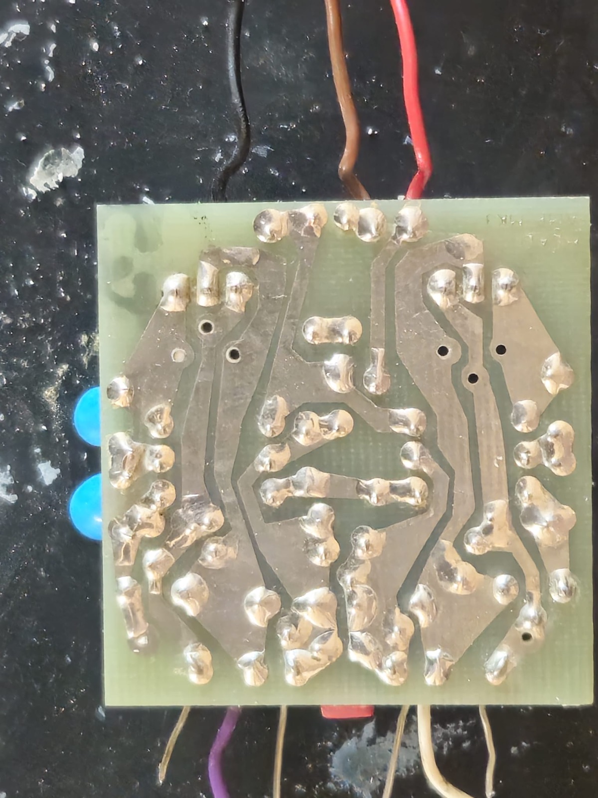
The solder side after the full reflow.
Afterwards the two channels measured +29.4dB and +28.8dB, within 0.5dB of each other and both on the published spec. Because the whole board was reflowed, we cannot point to the single joint that caused it, and we would rather say so than pretend we replaced a part. What we can say is that nothing original was replaced to fix it. The obvious expensive move would have been to dig out and replace the potted transistors, and they were never the problem.
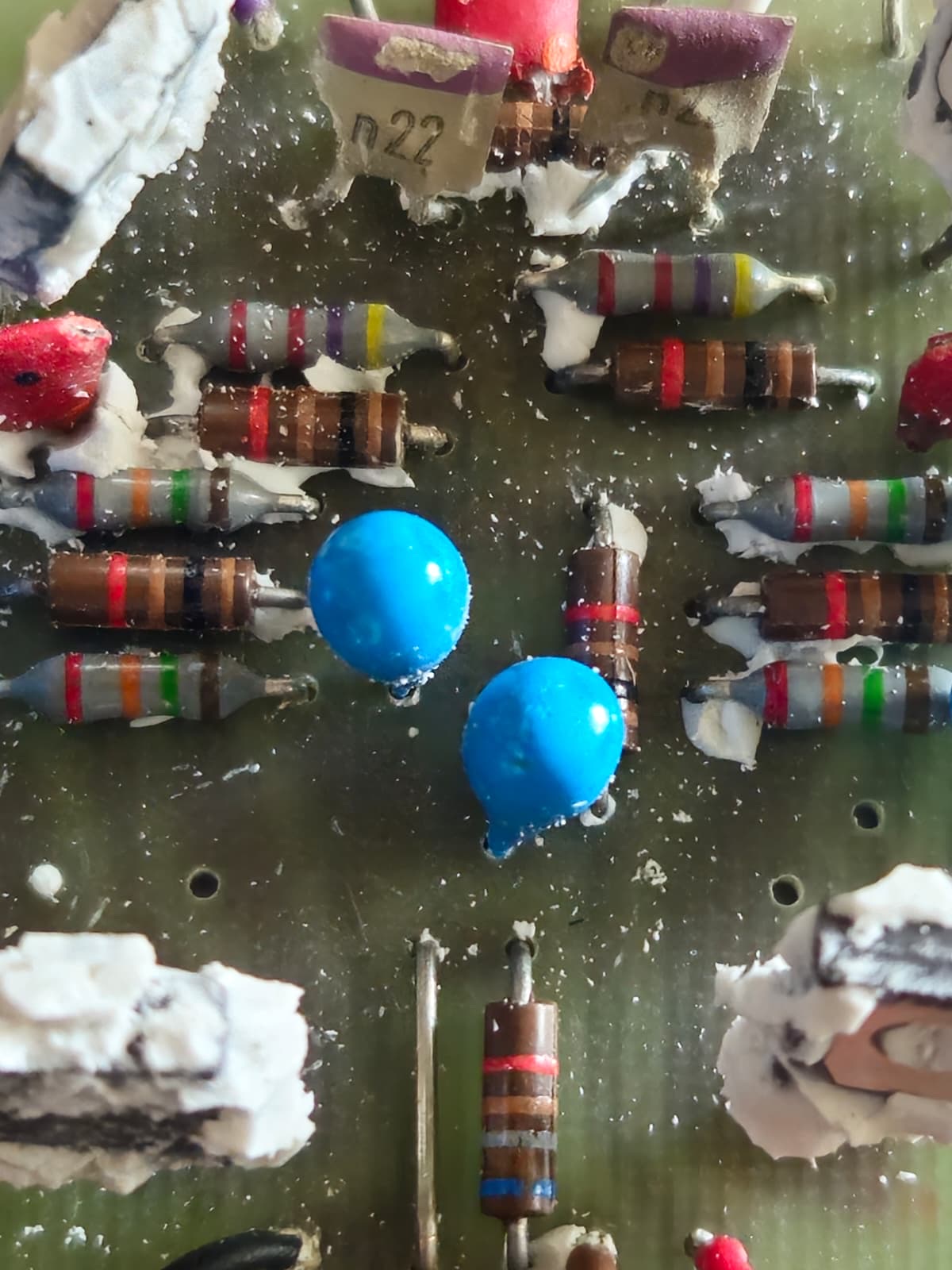
The two 220pF output capacitors. Both had physical damage, so both were replaced.
Signed off properly
- Left off overnight and tested from cold: both channels came up healthy within seconds.
- Tested again through the chassis sockets rather than the board wires: 0.3dB between channels.
- A listening test on a real system, with a centred stereo image.
While it was open we also cleaned the corroded on/off/test switch and replaced the two damaged 220pF capacitors, at no extra charge. Because the original potting could not go back, we 3D printed a new enclosure for the board, so it can be serviced in future instead of being sealed in silicone.
The £40 assessment was credited against the repair, as it always is.
Have an amplifier, phono stage or other vintage audio board with a fault nobody can find? See our soldering and board-level repair service. We quote before any work starts.